Figure 1
James May's Meccano Motorcycle & Sidecar
by
Peter Finney
(First published in the RMG Magazine - October 2013)
Readers in the UK will be familiar with the
BBC 'Toy Story' series featuring James May.
Programmes which stick in my mind include the full-size Airfix model
Spitfire, the Meccano Bridge, the Scalectrix race round-Brooklands race and the
Barnstable - Bideford scale 00 model railway race. (of course we must not
discuss the L**o house here!). The theme
of these programmes is to take a product designed as a child's toy and to do
something extraordinary or apparently 'impossible' with it.
Now I know that some of us don't quite
believe it, but there is no doubt that Frank Hornby first intended Meccano to
be a child's toy despite the undoubted fact that it evolved far beyond Frank's
original concept. Therefore 'Toy Stories'
has Meccano firmly in its sights.
Around the spring of 2013 rumours began to
circulate of an extraordinary project being planned by James and his team for
this winter's Toy Story Christmas special.
The idea was to build, from Meccano, a full size motorcycle and sidecar
which could carry two adults around the Isle of Man (IoM) TT course under its
own power. The TT and Manx Grand Prix is run on public roads over a course
33.733 miles long and rises from
approximately sea level to 1,385 feet (422 metres). The roads used are by no means smooth. The
lap record is 17 minutes and 11.572 seconds (131.671 mph) set by John McGuiness
during the 2013 Superbike TT Race.
It is clear that May and friends set
themselves a very difficult target in this project. As well as the obvious
problems in designing the vehicle, the scenario for 'Toy Stories' requires the
machine to be built and operated in front of the BBC cameras against a tight
timescale. In this case, the first hint
of the project came when May was seen in the IOM in the Spring of 2013 doing a
reconnaissance of the course; when interviewed, he said that this was for the
2013 Christmas Special. This was later confirmed
by the BBC. We now know that the project
deadline was the 90th anniversary meeting of the Manx Grand Prix
which was held in the IoM in August this year.
The rest is history; the vehicle duly appeared in Douglas IoM and
circulated the course, driven by James May with Oz Clark as passenger, in front
of the amazed and enthusiastic motorcycle racing fans. Subsequently, by good
fortune, the machine appeared at the Henley Meccano Gathering on 31st
August. This gave us the chance to photograph the machine and interrogate the
builders (Simeon Oakley and Simon McCoy). This article is based on my photographs
taken at Henley, and my discussions with the builders. In retrospect, I know I
missed some interesting points, but time was short and I was one among many.
Design Features
Structure
|
|
Figure 1 |
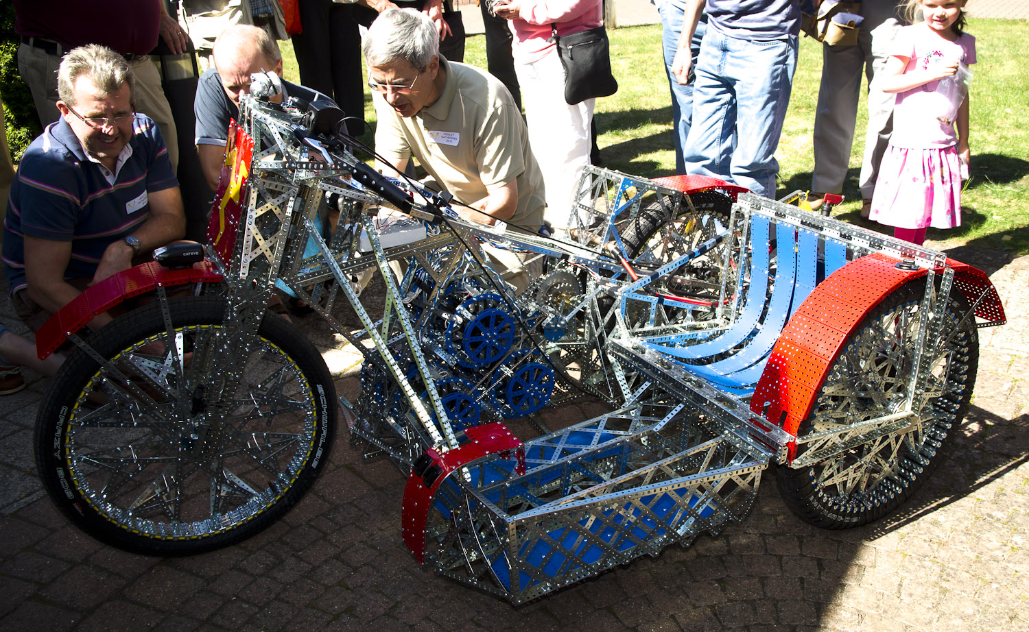
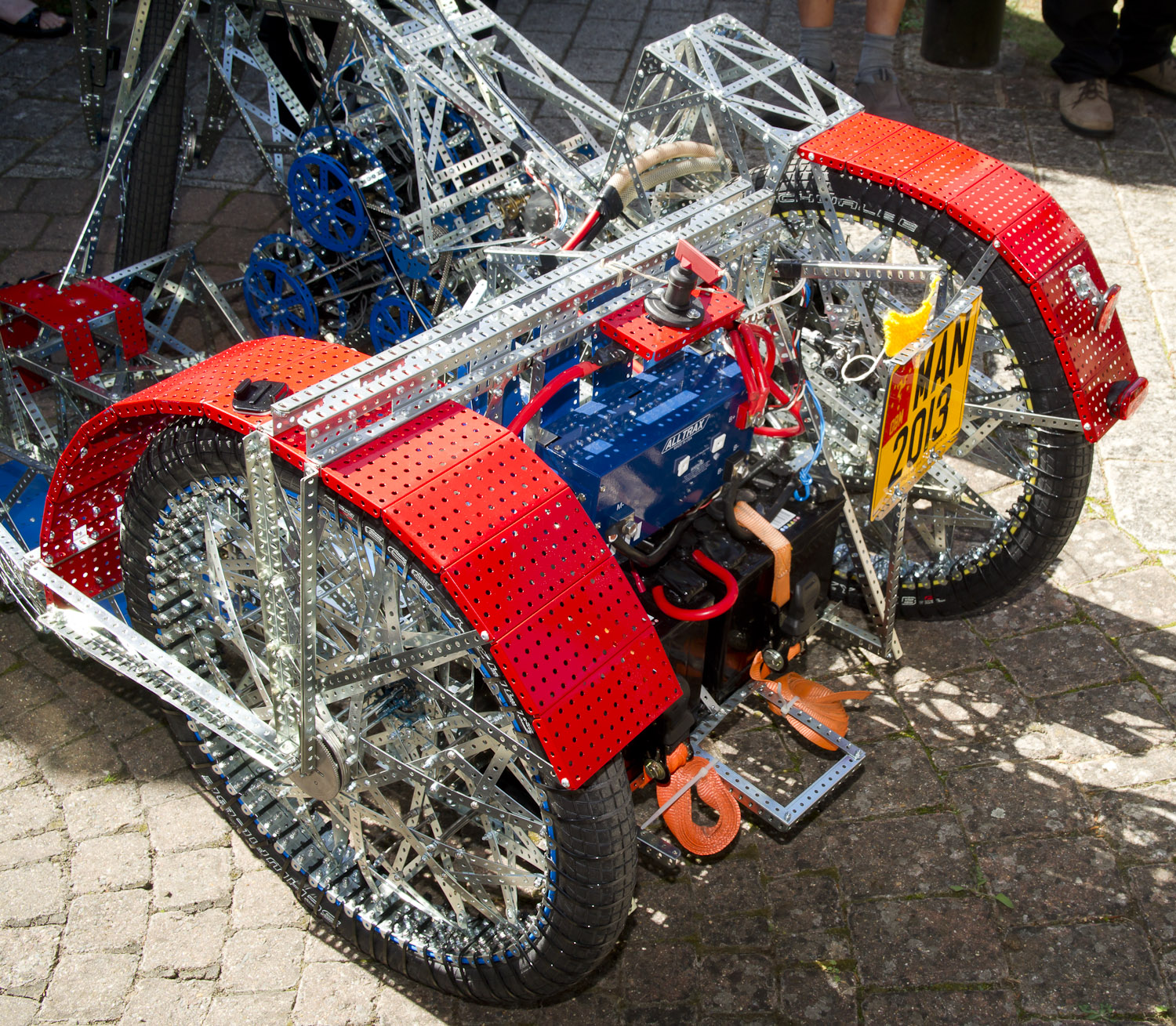
The structure (Fig 1).
is a conventional Meccano construction which gets its strength and rigidity mainly by using space-frame methods. Most of the structural members are basically
3-dimensional lattice girders with lots of cross-bracing. In many places angle girders are doubled-up
for extra strength. All the nuts used on the machine are self-locking (even so - I was told that nut tightening was the way-of-life on this machine).
 |
 |
| Figure 2 | Figure 3 |
Two areas of high load are particularlyinteresting. The first is the steering
head (Fig 2) which is built using a large number of flat trunnions clamped
together with long screwed rods and mounted to the front forks and frame by
angle girders. However, the integrity of
the design depends on the strength of a single meccano axle rod which is the
pivot! It looks to me as though it is
intended to be easily removable to allow the whole front fork and wheel
assembly to be removed. If that is to
work, the surrounding structure must be extremely rigid and well aligned.
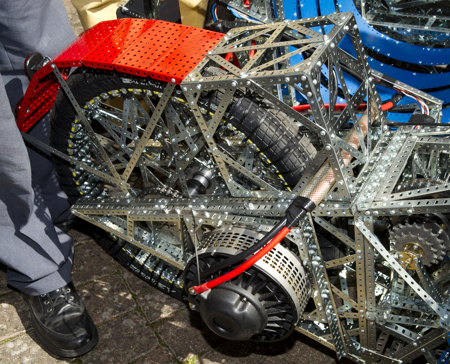
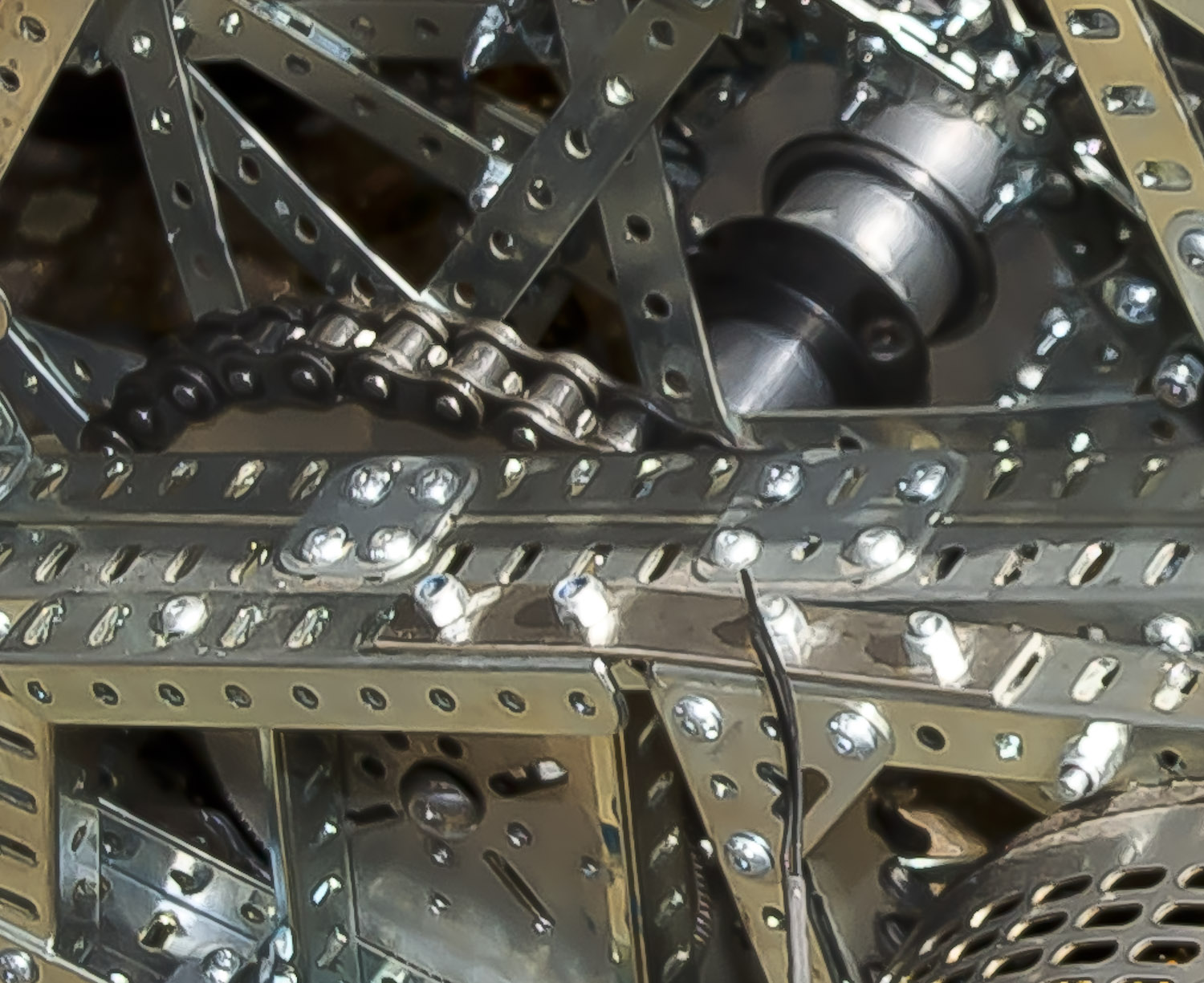
Secondly - the area around the rear forks
is the most massive structure (Fig 3). This is where the heaviest loads occur - the structure must support most of the driver's weight, transfer driving and
braking forces to the rest of the vehicle, and support side load from cornering. This is particularly difficult in a built up
structure using Meccano because of the many parts and the large number of
fasteners. There is a lot of shock
loading because the vehicle has no suspension (apart from the tyre compliance). This is a massive Meccano structure using
built up girders as the main elements.
Hubs, Wheels and Bearings
 |
|
Figure 4 |
It is clear that a genuine effort was madet o use Meccano parts wherever possible.
Obviously the tyres are not Meccano - they look like stock motorcycle
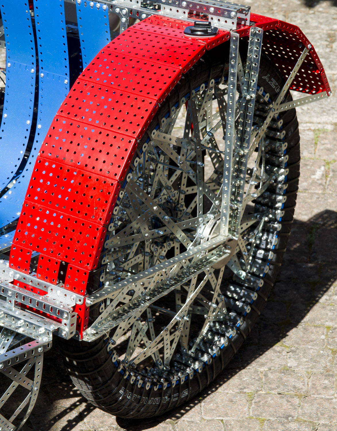
items. The wheel rims (Fig 4) are each built up from 4 rings of perforated
strips rolled to form circles - the 4 rings assembled side by side to make a
rim 2 inches wide. The rim lips (to retain the tyre bead) are formed by 1/2" by 1" angle brackets bolted to the rim
at 1" spacing. I suspect that some kind
of liner is placed inside the rim to protect the tyre inner tube from bolt
heads. There has clearly been a problem
retaining the tyres on the rims - each rear tyre is held on by a large number
of plastic cable ties! This is not surprising in view of the large side loads
generated by the tyre when cornering a motorcycle combination. The front tyre does not appear to have any
cable ties.
The spoke arrangement (Fig 4) is not like
any I have encountered before (but I may have had a sheltered life!) . It uses
a large number of perforated strips in a complex three-dimensional triangulated
structure. Screwed rods at about one half the rim radius are used to help
stabilize the structure axially. The
design process for this must have been interesting (we must wait for Christmas
to find out). This design clearly
serves its purpose; however on at least one of the available videos of the
machine in action it can be seen that one of the rear wheels is not true - this
must given extra excitement for the passengers. I suspect that a lot of the nut
tightening effort went into the wheels.
The hubs and bearings must have presented a
major challenge to the designers. This machine must be a lot heavier than a
minimum-weight design following best motorcycle practice. However a great
effort has been made to use a minimum of 'foreign' parts.
 |
 |
|
Figure 5 |
Figure 6 |
The hubs form an integral part of the
structural design of the machine, and are essential to retain the stiffness of
the three fork structures. In each of three cases the hub is based around 2
part no 27b 3.5" diameter gear wheels.
These are bolted to the fork structure at each end of the hub. On the sidecar and front hubs (Fig 5) the two
gear wheels are tied across the width of the hub by 4 screwed rods which pass
through the bearing inner races. On the
motorcycle rear hub this arrangement was clearly not strong or stiff enough to
deal with the loads, so there is a non-meccano solution (Fig 6). The main hub cross-member appears to be a
(modified?) proprietary item. Close examination reveals a large non-meccano
bolt passing through the part no 27b on the drive side of the hub.
 |
|
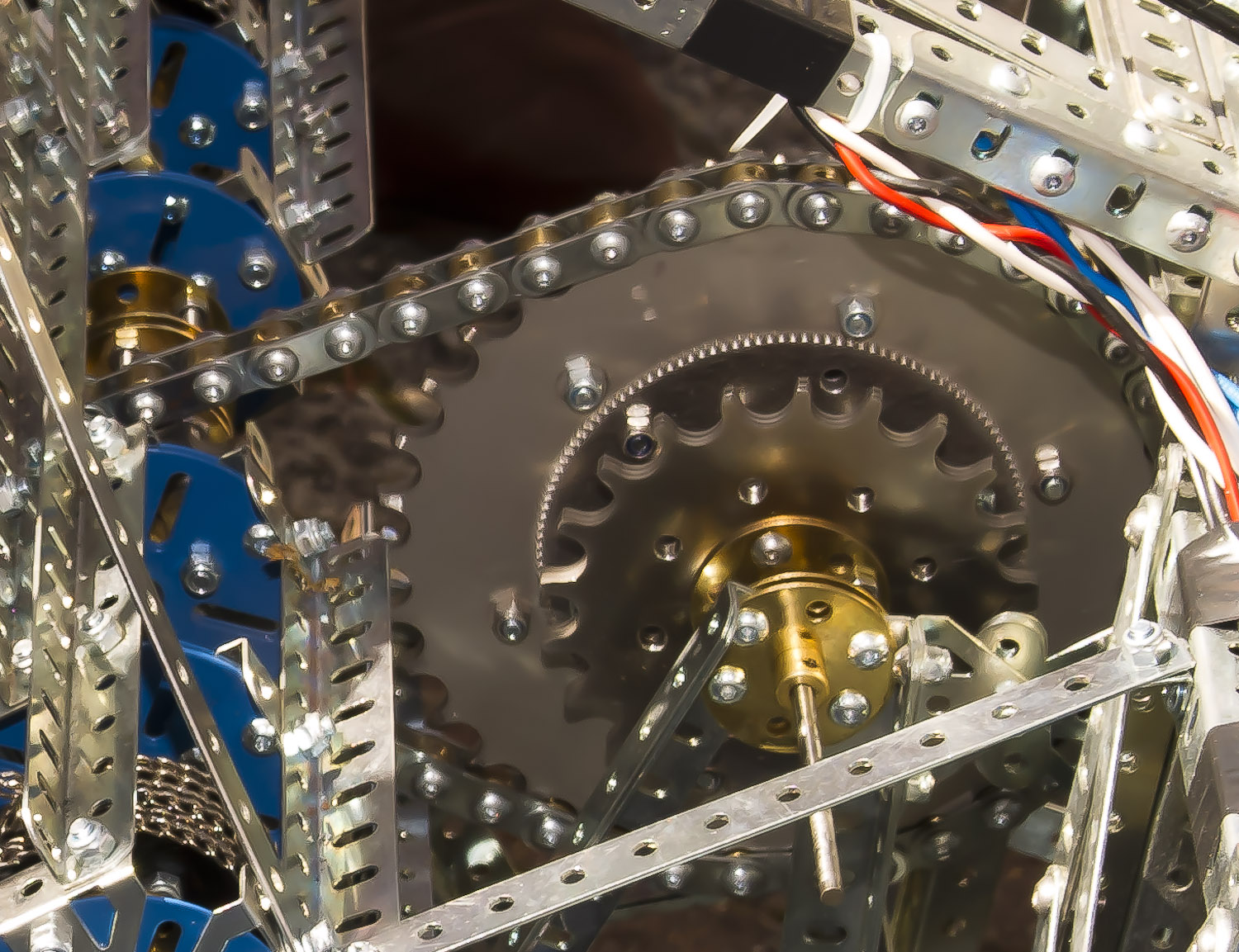
Figure 7 |
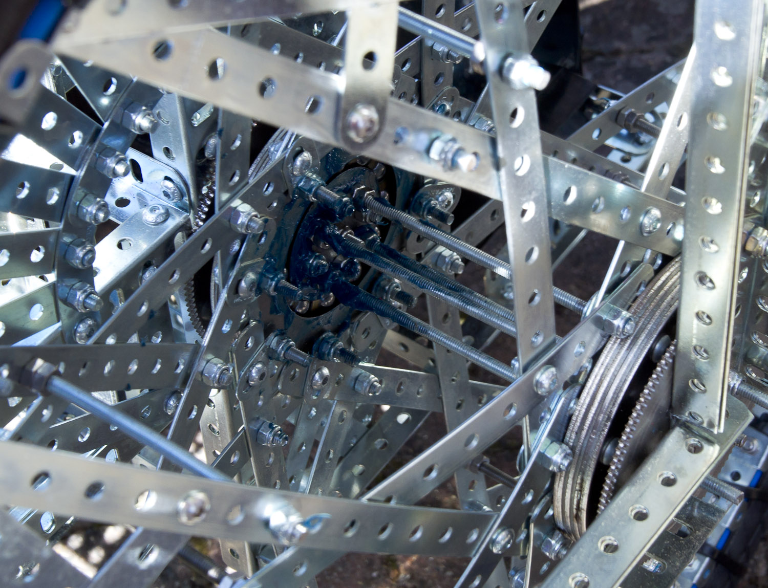
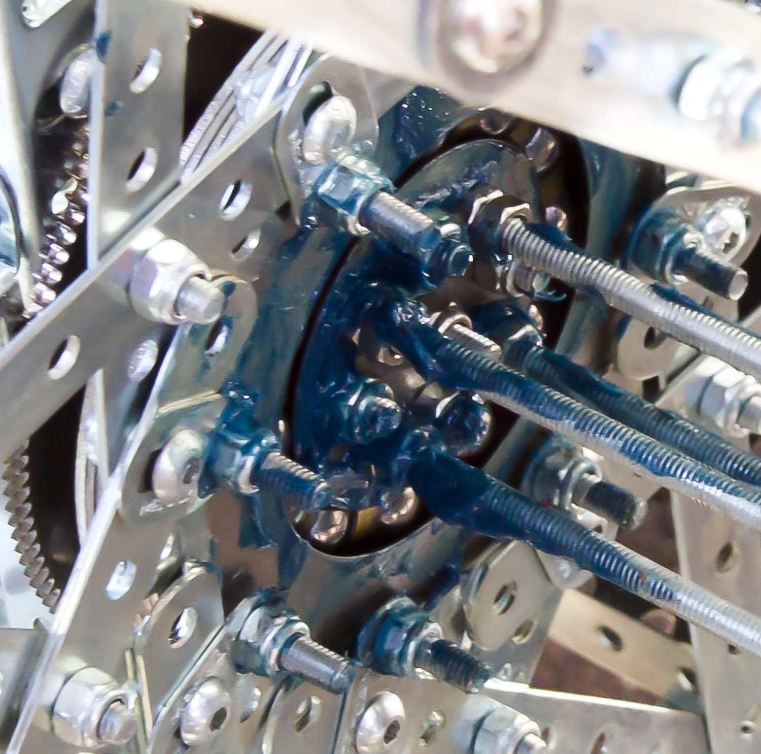
Available Meccano bearings cannot do the
job. (Fig 7 - the blue stuff is
grease) The bearing inner and outer
races appear to be built up from stacked steel laminations, possibly laser-cut.
However the balls are standard Meccano part No 168d (this was confirmed to me
by the builders), and it looks to me that they are spaced apart by part No 59a
aero collars.
Brakes
An effective braking system is essential
when negotiating the IoM Mountain Circuit!
This machine had to be licenced for use on the public roads (the story
of that is told elsewhere), and this required two independent braking
systems. I noticed that there was no
front brake, and queried this with the builders. They said that as originally
built there was a brake on the front wheel and one on the motorcycle rear
wheel. These were proprietary cycle disc
brakes. When the front brake was tested,
the entire front forks and wheel collapsed.
This not surprising - stability and rigidity of the front forks under
braking is issue on any motorcycle. They solved this by using dual calipers on
the rear brake - and persuaded the IOM vehicle examiner that that amounted to
independent systems.
Propulsion
It must have been clear to the designers
from the outset that it would be impossible to go round the IoM Mountain
circuit propelled by a system using standard Meccano motors and drive train
components. However it seems to have
been a design objective to enable the machine to run - at least on the flat - using standard Meccano components. They therefore adopted a dual-system
approach.
 |
|
Figure 8 |
The primary propulsion system uses a 3KW
electric motor, batteries and control system from an electric golf buggy (Figs
3 & 8). The motor drives the rear wheel via a 1/2" pitch roller chain and sprockets
(non-meccano). It works. I suspect that this was used nearly, if not all, the
way around the circuit. The builders claimed that it was only for 'going up
hills' - I doubt that ; no doubt we will find out at Christmas.
What I will call the 'Meccano propulsion
system' is fascinating and pushes Meccano to its limits. Meccano do not provide any 'large'
electric motors. Although the current
Meccano permanent magnet motors are very efficient - they are small. But those
were what were available. Solution - use lots of motors, 96 motors to be
specific! By coupling 96 Part No 700 motors together, the designers were able
to propel the machine, with passengers, on the flat!
But - how do you couple 96 motors together
in the space available? This is how.....
 |
 |
|
Figure 9 |
Figure 11 |
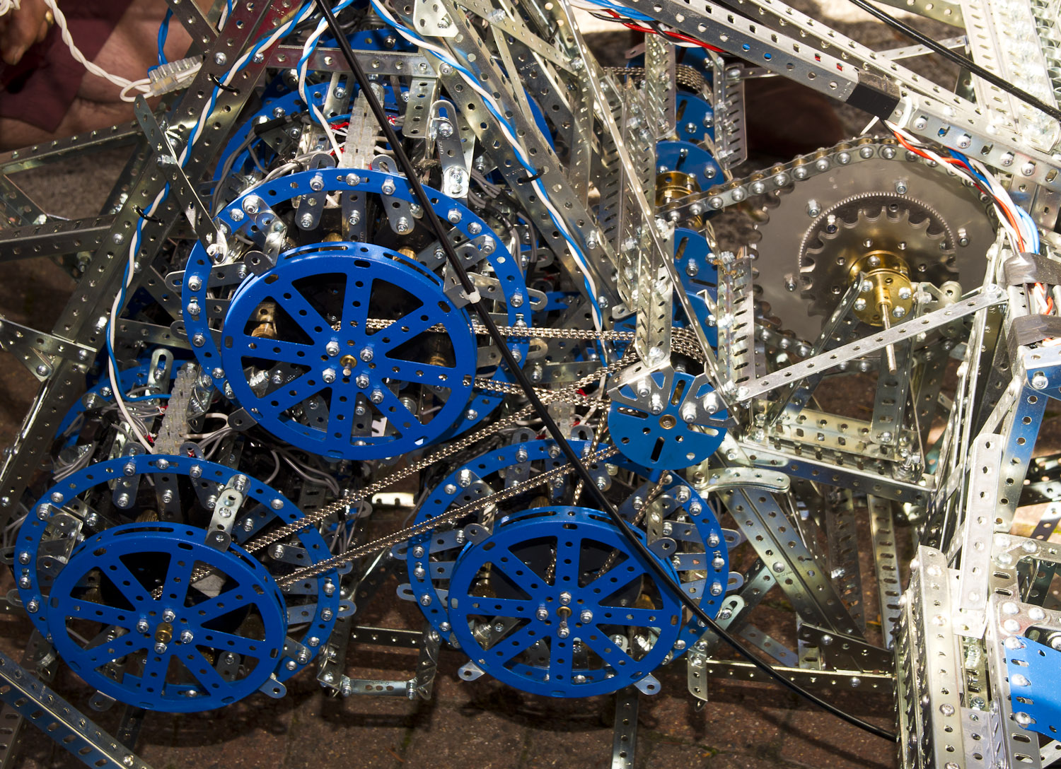
The Meccano power unit is modular. It
consists of 6 identical modules, each containing 16 motors. The modules are
arranged symmetrically, three on each side of the machine (Fig 9). Each module
is connected to a primary layshaft using standard Meccano chain and sprockets
(Yes - 16 motors driving through each chain!).
The primary layshaft connects to a secondary layshaft using non-meccano
sprockets and a 1/2" pitch roller chain built up from standard Meccano parts (1"
narrow strips, collars. pivot bolts and self-locking nuts ... I believe) (Fig11). The
secondary layshaft carries several different-sized sprockets which could be
used to drive the rear wheel by another chain.
 |
|
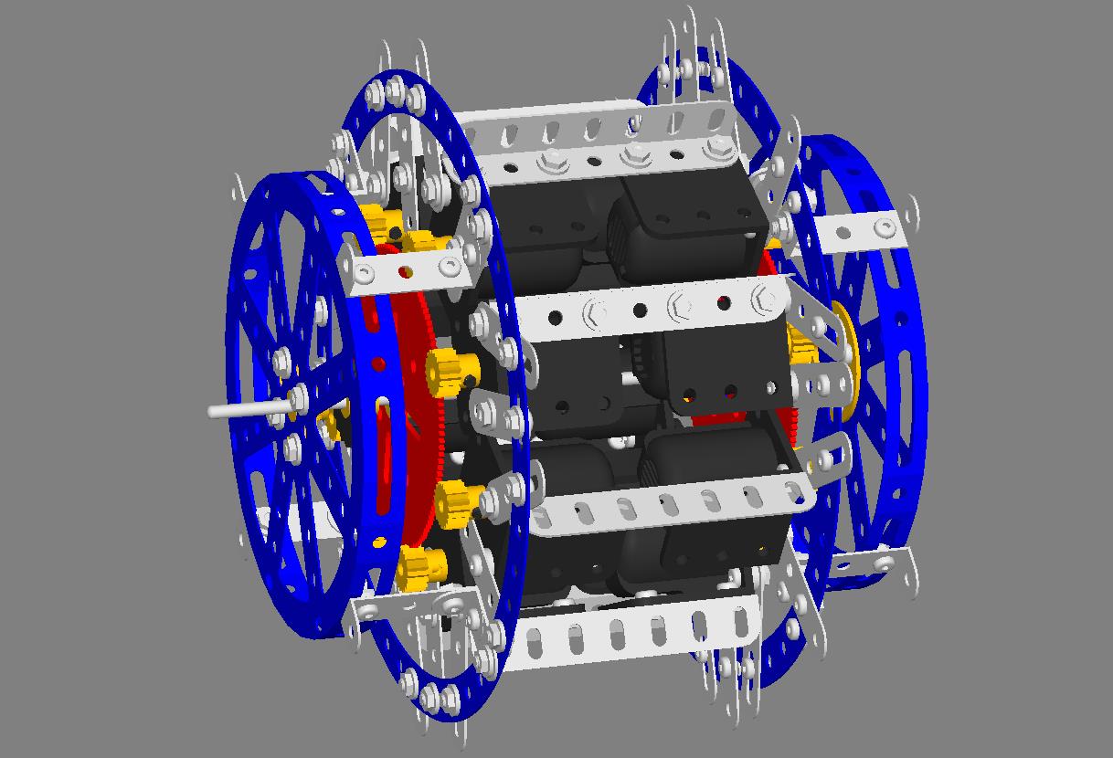
Figure 10 |
To explain to construction of one of the 6power modules I have constructed a Virtual Meccano model (Fig 10). The motors
are bolted in pairs to 7 hole angle girders. The pairs of motors are arranged
symmetrically around a central axle rod carrying a Part No 27b 3.5"gear wheel
at each end. Each motor carries a Part No 26 pinion to mesh with one of the
gear wheels. The module is held together by two part No 145 circular strips
which support the motors by strips and slotted strips. The meshing of the gears
is adjusted via the slotted strips. I
believe the disposition of these mounting strips is determined by the need to
leave holes vacant in the circular strips to allow the power modules to be
mounted in the motor cycle frame (Fig 9).
The central axle rod carries a meccano sprocket to drive the primary
layshaft and is journalled at each end in a bush wheel bolted to a Part No 118
Hub Disc. The hub discs are mounted to
the circular strips using double angle strips and angle brackets.
If you try to build one of these modules you will find that the motor mounting bases (plastic) will foul on the inside (adjacent to the central shaft). There are two possible solutions to this::
I do not know which solution the designers used (I suspect No 2 - which is what I have done in the virtual model).
There are some obvious issues with this
design. The structural integrity of the
whole thing depends on using the plastic cases of the motors to link the angle
girders and the motor mounting strips. That could be problematic - particularly
if the motors got hot. Good ventilation is essential, so do not mount this in a
confined space! The life of the (brass)
pinions is likely to be short and spectacular. At Henley the builders fired up this power
system (not connected to the final drive); it certainly made a joyful sight and
sound with all those chains and sprockets wizzing around; but then the designer
pointed out all the 'gold dust' which was coming off the pinions as they were
being 'modified' by the steel gear wheels.
There did not seem to be much visible wear on the pinions, which
suggests that the vehicle had not travelled far on Meccano power. I this were to be used for long periods under
heavy load it would be essential to substitute gear wheels with wider faces
(possible using one of the Delrin solutions).
I'm also a bit dubious about the bearing arrangements for the central
shaft. It's a long way between those
bush wheels!
I do not know how the motors are connected
electrically, but there must be some kind of series-parallel arrangement. When
it was demonstrated, the speed was controlled by switching, which suggests the
there are several series-parallel steps for starting. The designers stated that the total power
output was about 0.6 hp (about
500w). I don't know how accurate that is
or whether it represents mechanical output or electrical input.
Non-Meccano
Parts Summary
Is this a motorcycle and side car made entirely from Meccano, that can go round the IoM Mountain Circuit under its own power with a driver and passenger? - obviously not.
Can it run at all under meccano power? - yes.
for how long? - who knows!
Does the above matter? - I do not think so. I think it is up there with the Brooklands Scaletrix race, and the long-distance 00 Gauge Railway Race , and may well be the best 'Toy Story' yet. It certainly got the approval of the crowd at Henley. I believe it will generate a huge interest in Meccano when shown on TV.
Meanwhile, if you want to see it in the flesh you will have to visit the Meccano museum in Calais.
Video Clips
There are quite a few Video clips of the machine on the IoM, you can find most of them, plus a lot of other publicity material, on the Meccano UK Twitter feed, here:
https://twitter.com/Meccano_UK
 |
Go to Meccano Index Page |
 |
Peter Finney's Home Page |